
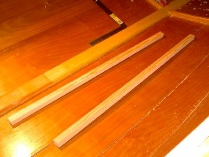
Here are some of the parts needed to get started on the bilge board cases. The plywood is half inch and the beams are 1 1/2 inch square. The full size plans sure are a big help for this procedure.
The marks on the hull aren't visible in this shot, but they're there, 17 (should've been 18...oops) inches outboard of the centerline of the boat. Here I have made the lower bilge board case logs and am getting an idea of the fit and how much force will be needed to bend them into place. I'll glue the pieces into place and use the router to cut a flush slot in the hull. From there, it should be a simple matter to assemble the cases in place.
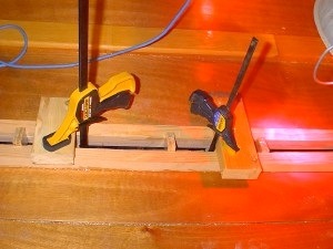
The inboard logs were the first ones glued into place. These ones were pressed into place along the curve of the hull by using sticks wedged against a piece of wood clamped across the boat's gunwales. Then a router was used to make the first cut for the slot using the frame as a guide. The slot was then opened up a bit to fit the clamps as shown above. I've clamped the second pieces like this (inside and out) to minimize hull distortion and use the first log as a support for the clamps. I was back to using heat lamps for a few days as the temperatures dipped a little.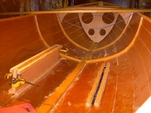
Once all the lower bilge case logs are glued into place and the slots opened up, the bilge board cases can be tried in place. At this point the cases were just clamped together in case some major "adjustments" were needed. None were and a little work with a block plane and a wood rasp was all that was necessary for a good fit. As the cases are angled toward the centerline and the tops are horizontal, the full sized plans were invaluable in getting the cases set up correctly.

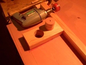
As the photo shows, some of the initial assembly work has been done. The case sides are cut to fit the slot in the boat and the top rails and intermediate vertical frame members are in place. A pilot hole (the same size as the pilot bit on the hole saw) is drilled through both case sides, centered on the wide bearing support and adjusted to suit the bilge board. I made a "dummy" board from cheap wood product to test the fit and clearances.
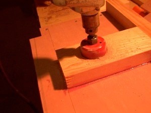
Now a hole is cut with the hole saw. This is a 2 1/8 inch saw and seems to be about right for the boat. The diameter is somewhat larger than shown on the plans. It will also make drilling the bilge board pin hole a little less critical.
Although I cut the hole from both sides as far as the saw would go, I still needed to give the plug a good rap with a hammer to loosen it. Of course this needs to be done for both halves of the case.
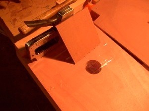
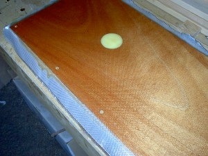
So now we have the hole for the epoxy bearing cut, the back is taped over with packing tape and a backing of cardboard is stapled over the hole.
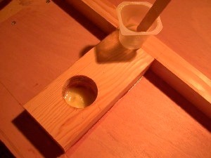
The case side is then flipped over and a thickened mixture of resin and WEST 406 is poured into the hole and any air bubbles carefully removed. I did about a third at a time ensuring there is no excessive heat build up as the resin mixture fires off. I didn't do this the first time and got some practice chiseling and cutting the mess away. Again, this has to be done for both sides.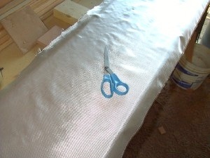
Once the bearing for the bilge board pin has been formed, it is sanded flush with the surrounding wood. Now the insides of the case is draped with fiberglass cloth.
The cloth is then wetted out with resin and trimmed before it gets too hard. I used silicon bronze screws to assemble the cases in addition to gluing.