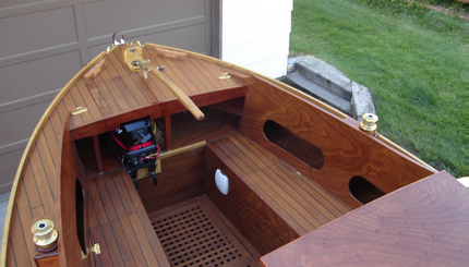
Alan put this list of small errors he noticed on the plans for the boat. As always consult the designer first, and use this information at your own risk.
Alan's Comments
A Site for everyone interested in Iain oughtred's eun mara sailboat design

Alan put this list of small errors he noticed on the plans for the boat. As always consult the designer first, and use this information at your own risk.
Alan's Comments
(This information is provided "as is" to builders for their information only. We cannot be held responsible for any problems you may have. As always, if in doubt, consult with the designer.)
Sheet(s)
2
The inner stem is indicated to be 2 1/4” sided or 2 3/4” molded. In other places (i.e., outer stem and sternpost) the molded option is indicated to be thinner. Its seems that his should also be the case for the inner stem.
6 & 7
On Sheet 6 the mild steel rudder plate is specified as being 1/2” (in two places) whereas Sheet 7 specifies 3/8”. The 3/8” seems correct as Sheet 7 shows the gap for the plate to be 7/16” (too narrow for a 1/2” plate).
4
The bowsprit mastband is specified to have two eyes. This is correct for the rectangular bowsprit shown in the drawings. However for the 2 1/2” round bowsprit mentioned in the Sheet 4 note, four eyes are required.
4 & 6
The Rigging List notes a 5/32” 7x19 wire for the bilge hoist line. Sheet 6 notes a 3/16” rope bilgeboard hoist which seems adequate for a high strength low stretch line. The 5/32” line may not wrap well on the 3/4” dia bilge hoist drum.
6
Pivot holes of 1/2” diameter are specified for the bilgeboards and rudder plate. These holes should be drilled slightly oversize so that after galvanizing the holes will easily accommodate the 1/2” pins.
2 & 7
The holes for the lead ballast are shown as being staggered on Sheet 7 and are shown inline on Sheet 2. The staggered arrangement is probably correct.
3
The motor well is shown to be on the starboard side. If the motor has its handle on the port side, then it may better to locate the motor well on the port side. This way the top portion of the motor will offset away from the center of the boat. Another option is to remove the handle and provide another means for controlling the throttle.
2 & 5
In Sheet 2 the dimension for the cabin roof beams is given as 1 1/8” x 1 1/2”. In Sheet 5 this dimension is given as 1 1/4” x 1 1/2”. As in both places the dimension is also provided as 30 x 40 mm, 1 1/8” seems to be the correct dimension.
4
The furling gear is noted as being “Wykeham-Martin Size 2B”. In the current catalog this is just “Size 2.”
7
On Sheet 7 the Classic Marine HL 0228 and 0299 medium duty rudder are noted to have 1/2” pintles. In the current catalog these are probably HL-2242 and 2211 which are for 3/8” pintles.
2 & 5
Sheet 2 and the Materials List show the carlins as being 1 by 1 1/8” (both the carlin in the cabin and in the cockpit) whereas Sheet 5 shows the carlin in the cabin as being 1-inch square.
2
The mast beams are shown to be both 3 3/4” and 3 1/2” wide.
11
The curve for the aft deck beam at Station 8 has the baseline intersection noted as “Stn. 9;” it should be “Stn. 8.” Likewise, the curve for the aft deck beam at Station 9 has the baseline intersection noted as “Stn. 8;” it should be “Stn. 9.”
List
The Materials List show the bilge keel rails to be made our of 1 1/2” sq stock. Because the lower rails must be cut to follow the curve of the hull they must be made from wider stock.
Considerations
The cockpit floor is shown to slope forward to follow the shape of the keelson. This makes for a rather low floor at the fore end which may be uncomfortable (i.e., feet won’t reach the floor).
Add scuppers to the fore extensions of the cabin sides and too the small similar aft extensions of the cockpit sides.